Add a pitch mod and line-in to a brand new, inexpensive tape player

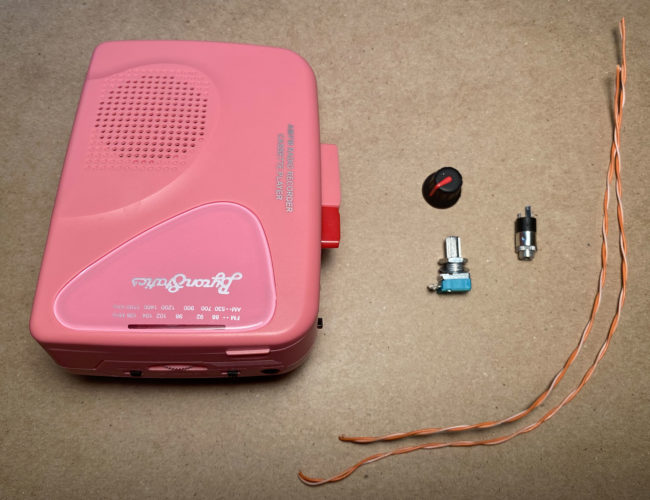
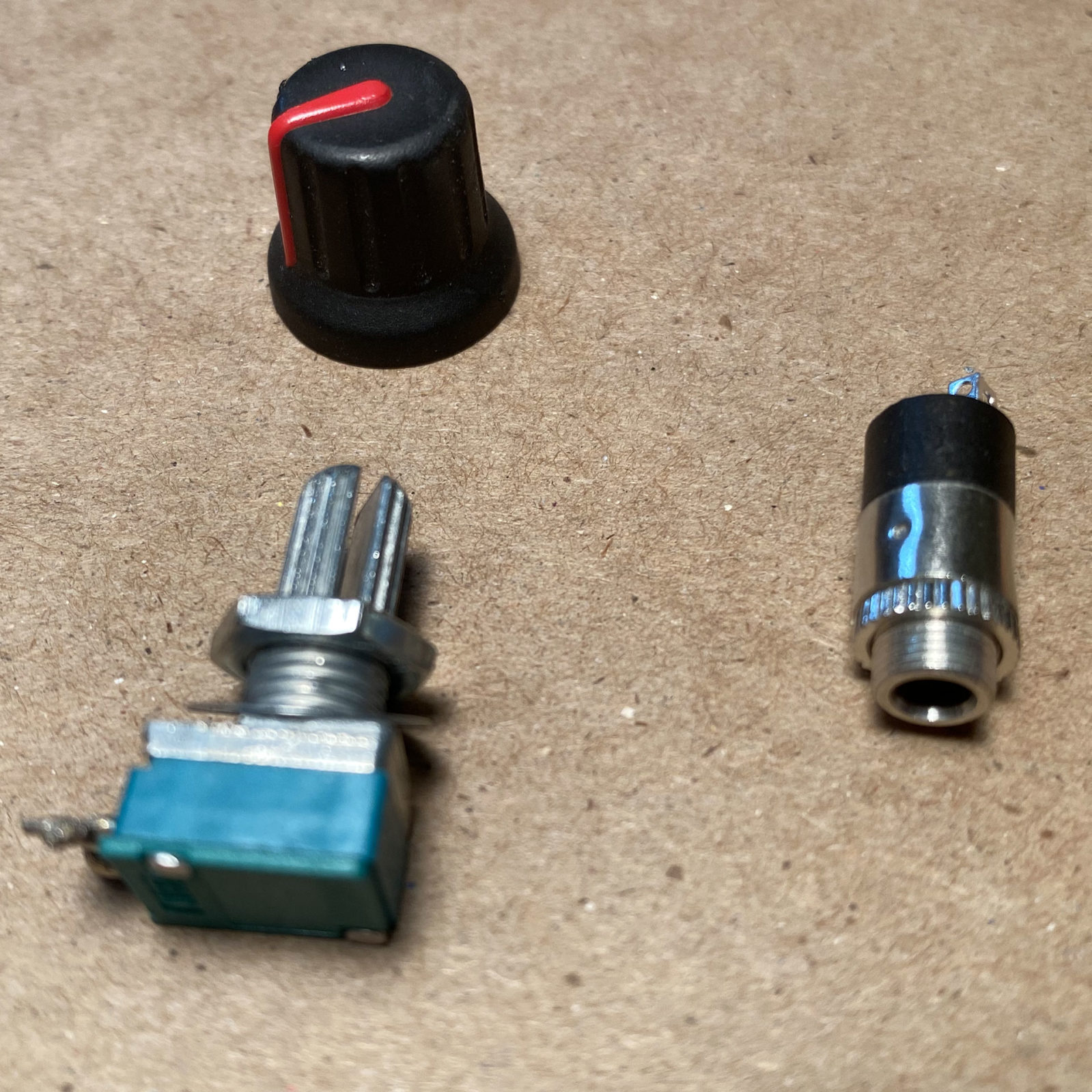
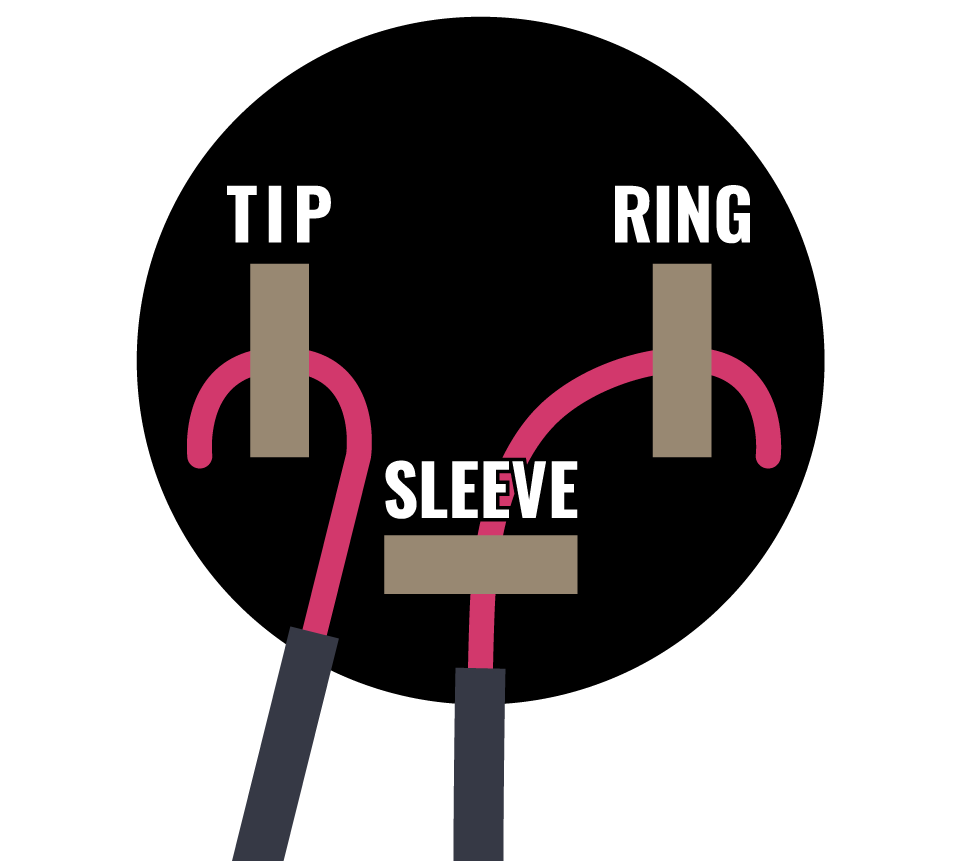
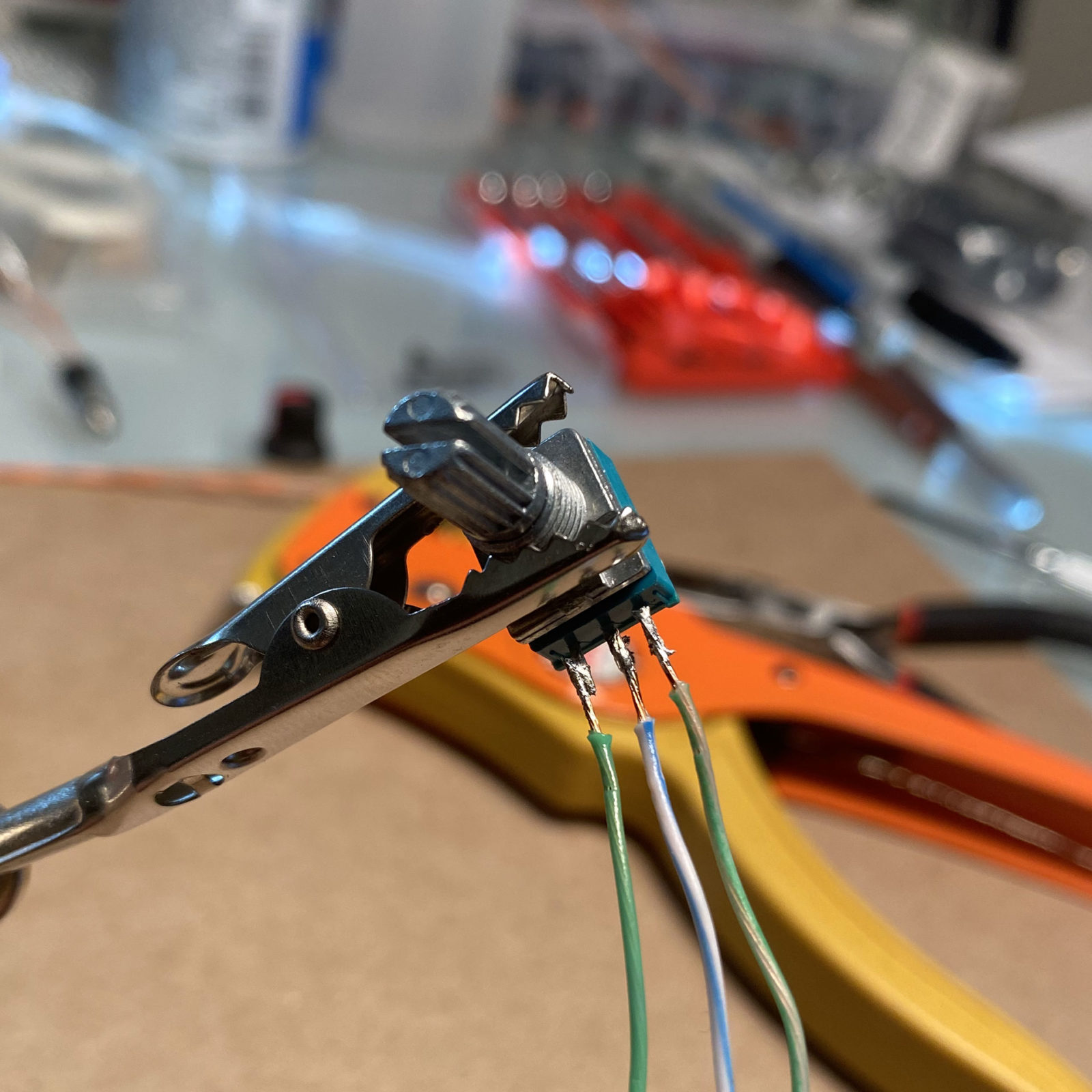
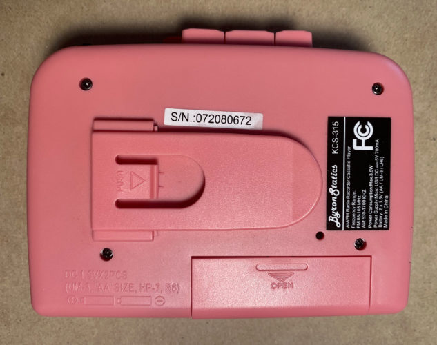
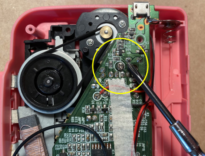
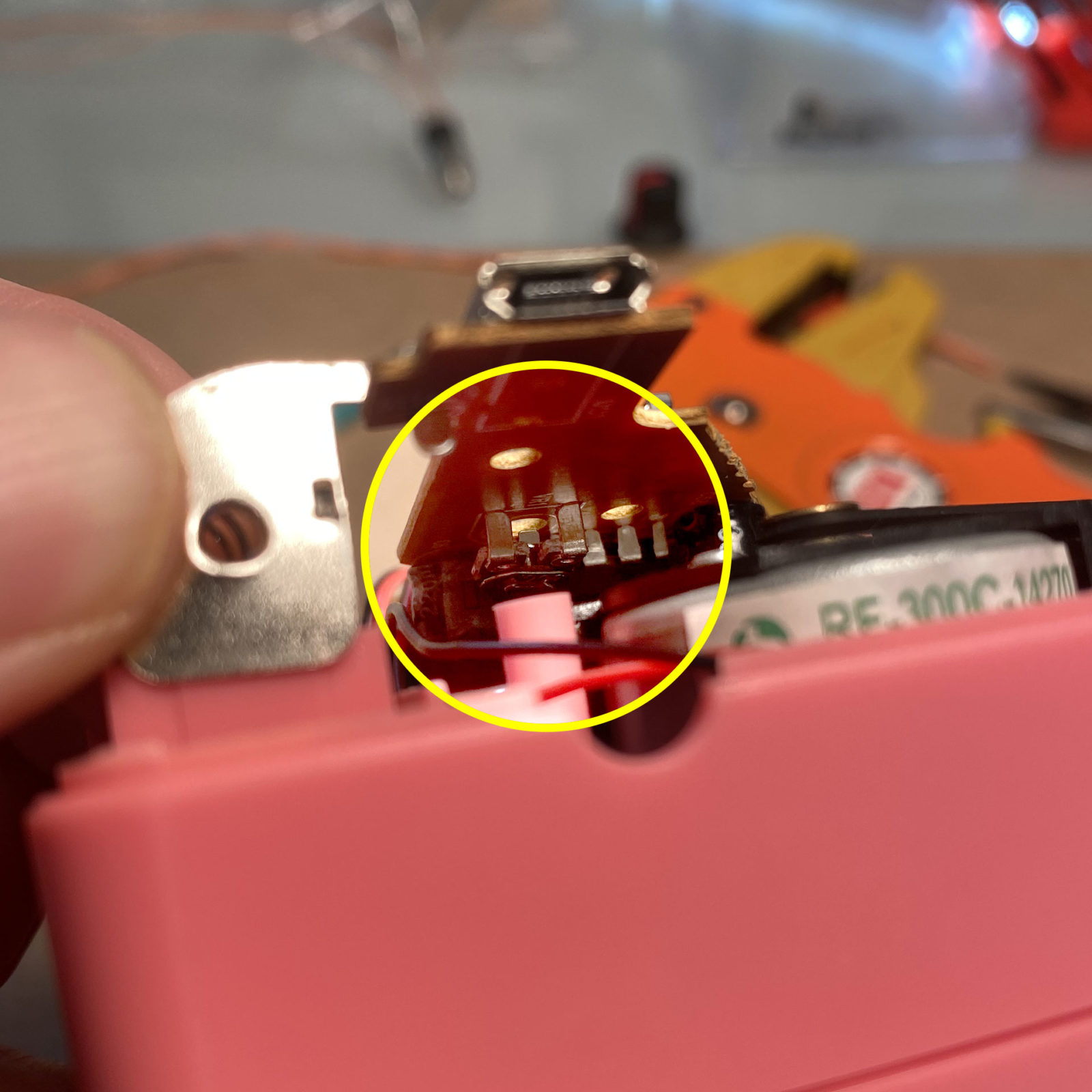
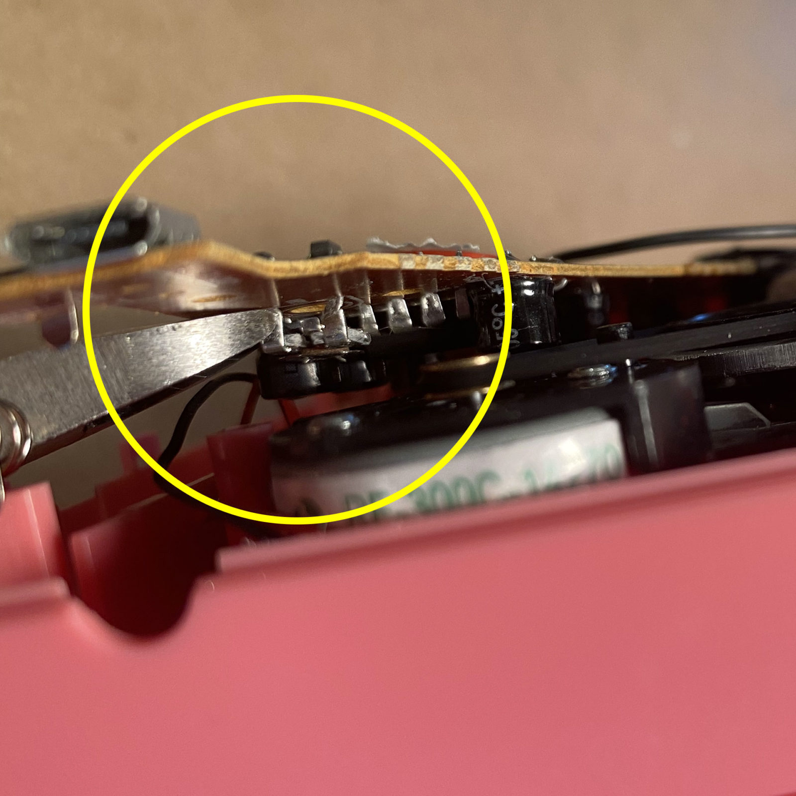
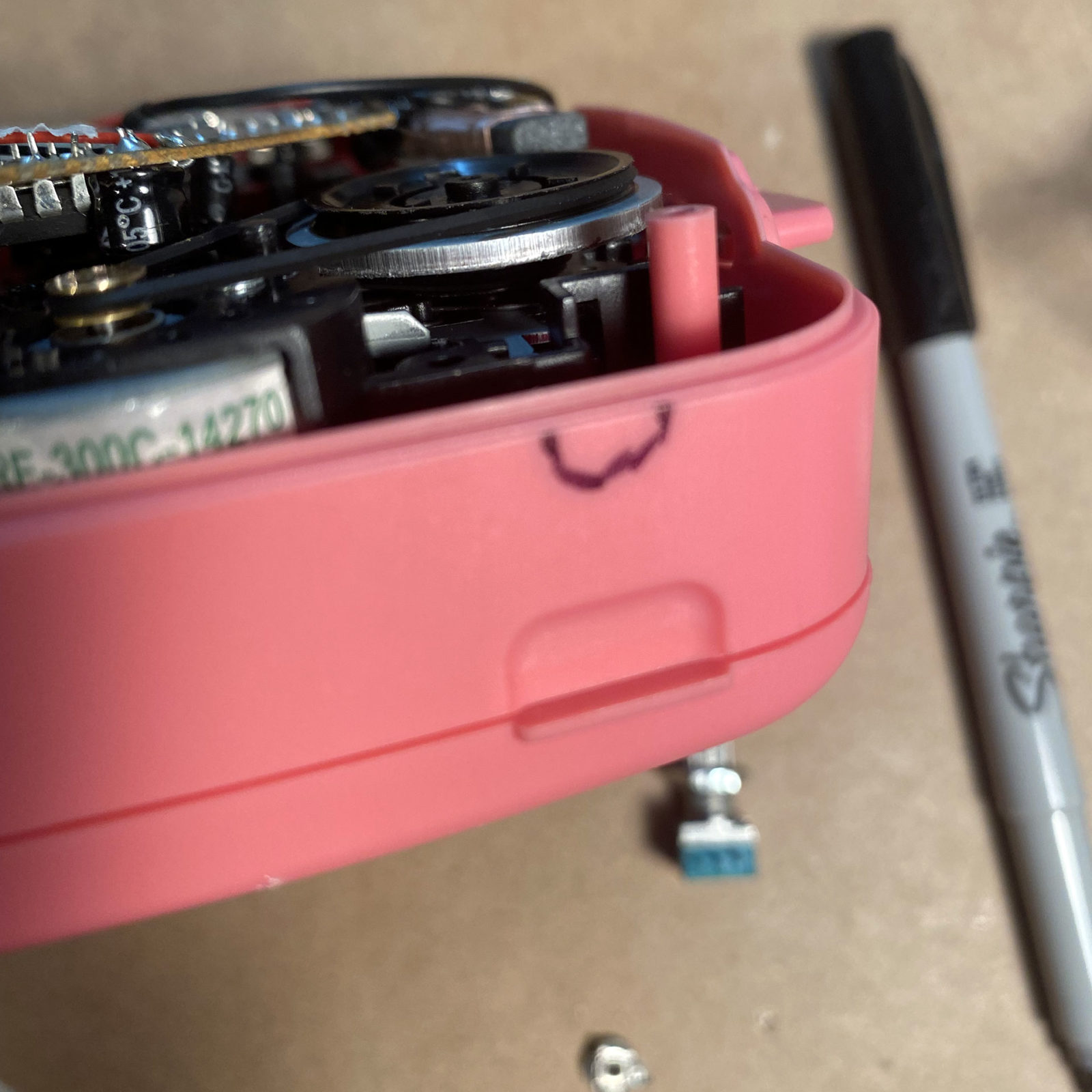
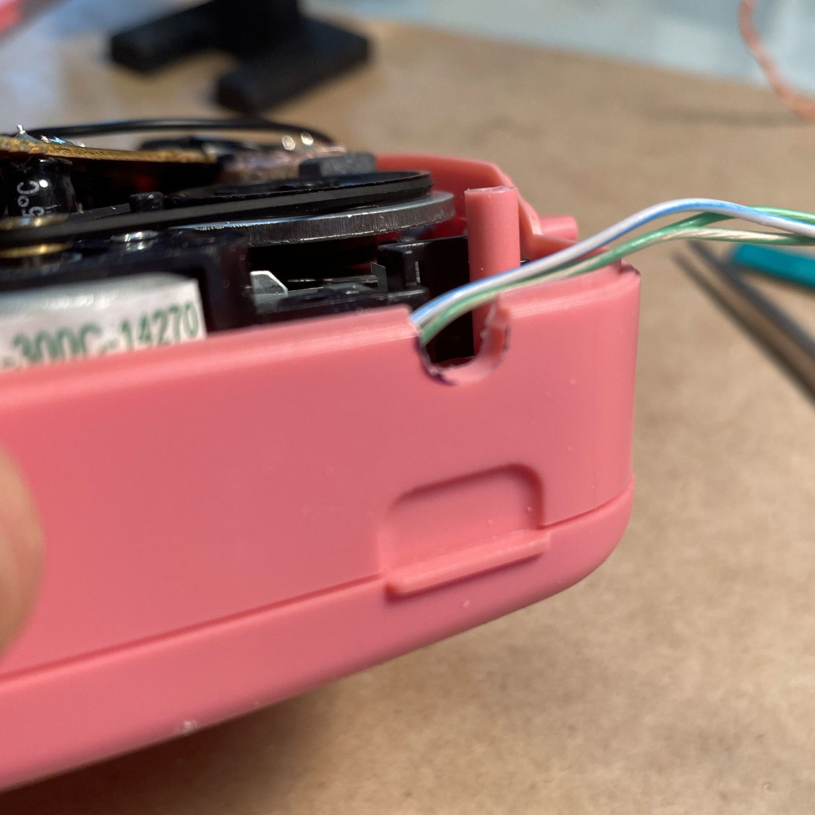
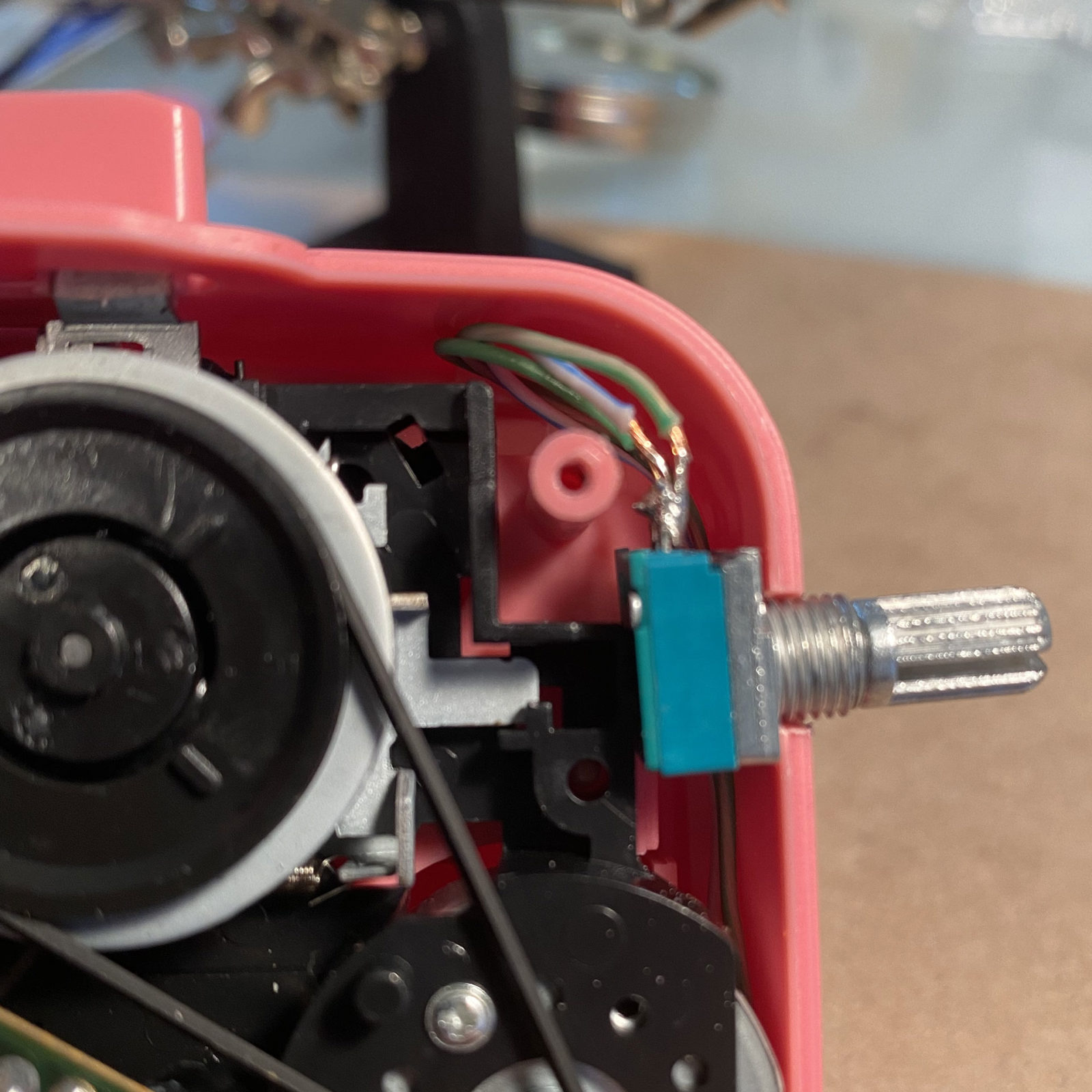
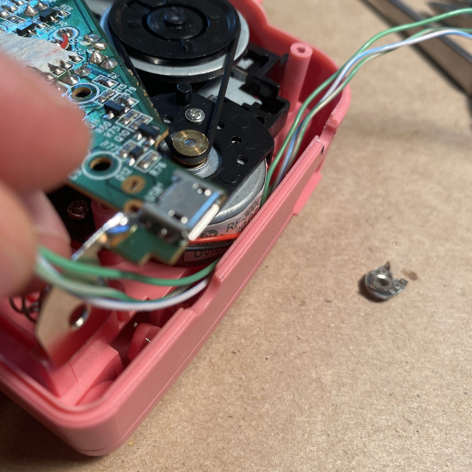
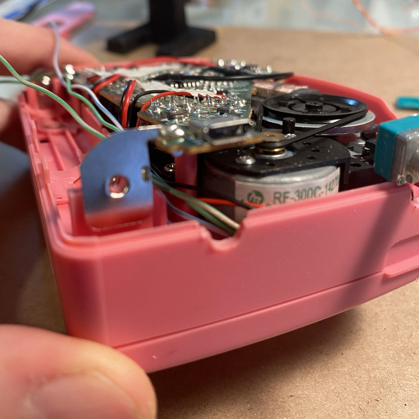
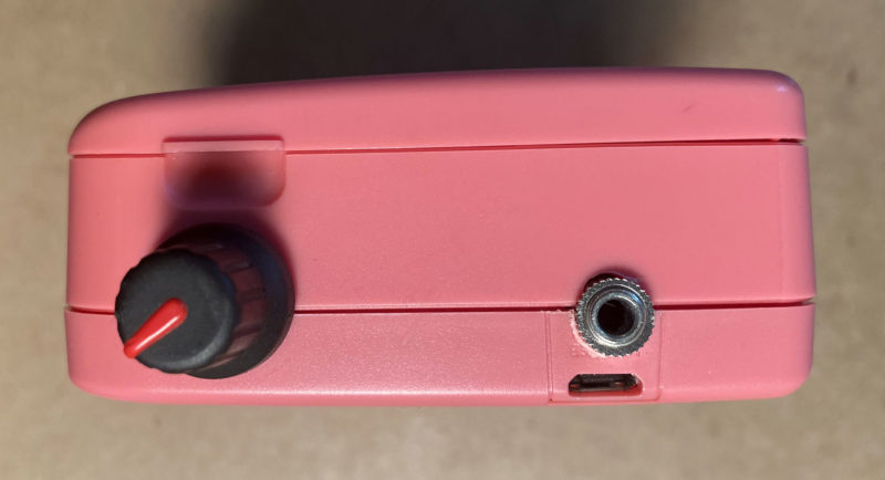
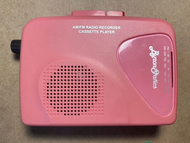
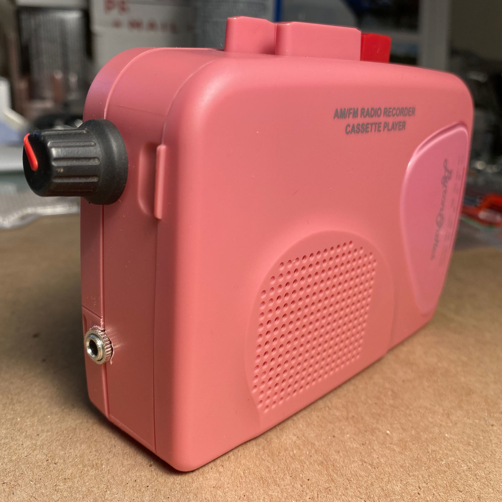
Okay, so I learned how to make loop tapes for use with my 4-track, but I wanted to add some simple stereo looping cassette decks to my live rig. With my 4-track, I use the FX sends to add a bunch of reverb and delay, and sometimes you don’t want or need sounds to be drenched in FX, like drums for example. So after building a “The Sound of Machines” modified cassette player tutorial, I figured I could start modding cassette walkmans. I only found one at a local thrift store, but it lacked many of the record features, but it seems like all the tape loop artists love the Byron Statics walkman – and the LOUD colors variants are just a bonus. So here’s my documentation on how to add a simple pitch potentiometer and a 3.5mm mono line-in.

Tools list:

  • Soldering Iron and Solder
  • Dremel Rotary Tool
  • 1/4 in. Dremel Tool Aluminum Oxide Pointed Cone Shaped Grinding Stone I find this tool more forgiving than using a drill, when modifying the plastic case. Drill bits tend to seize up, causing the case to spin and/or shred the plastic.
  • small Phillips screwdriver – you know, the small ones for fixing eyeglasses
  • small wire cutter
  • Self-adjusting wire stripper – I don’t have this exact model, but this makes stripping the ends of wires a cinch.
  • plastic pry bar – I picked up a couple of these years ago when purchasing kits to swap batteries on old iPods back in the day.
  • electrical tapeoptional
  • small tweezersoptional
  • small needle nose pliersoptional
  • cassette tape – for testing your completed mod

Parts list:

  • Byron Statics Portable Cassette Player – I prefer the blue, aesthetically, but it also comes in black and pink. Do not buy the black and white version, which is meant for converting audio to mp3s. This tutorial does not use that model player.
  • Single Linear Rotary Seal Amplifier Potentiometer B5K Ohm – It is important that you buy this style of potentiometer. There is not enough room inside the case for the more common potentiometer with a round base.
  • 3.5mm Stereo Jack Panel Mount Connector – this will be used to add a line-in option to your tape player.
  • Knurled shaft Potentiometer Knob – this is a 100pc kit, but try your local hobby shop. In Milwaukee, I’ve gotten these from American Science & Surplus.
  • A 6-10″ length of old ethernet cable – you’ll strip this to get to the individual wires within. These super thin wires work great because there’s not a lot of room inside the case. You’ll see.
  • Two AA Batteries (or USB cable) – because the cassette player doesn’t come with batteries or a USB cable for power.

Click thumbnail images to view larger and additional descriptions.

Prepare the components:

Prepare the 3.5mm line-in:

stereo to mono diagram

  1. Strip your ethernet cable outer wrap to get at the individual color coded strands. You’ll need Two 6-10″ pieces of wire.
  2. Check out this article about how to turn a stereo 3.5mm jack into a mono jack. The mic on this cassette player is mono, so you must convert the jack to work with mono signals. Solder the sleeve and ring terminals with the same single wire. Solder the tip side separately. Wire it like this.

Prepare the B5K potentiometer:

  1. Strip your ethernet cable outer wrap to get at the individual color coded strands. You’ll need three 6-10″ pieces of wire.

Click thumbnail images to view larger and additional descriptions.

Open the cassette player

  1. Remove the belt clip from the back of the player.
  2. Remove the four screws from the back, and place them somewhere safe.
  3. Pry apart the case. Be careful around the volume slider. If you have one, use a small plastic pry bar to gently pull the case from around the volume slider.

Click thumbnail images to view larger and additional descriptions.

Clip out the on-board trim potentiometer

  1. Remove the remaining screw attached the board to the case and lift up the board so you can access the trim pot. Only pull up the one side just enough to access the trim pot. Don’t remove the entire board, as you’ll have a harder time re-assembling, and you might mess up how the radio tuner lines up to the numbers on the case.
  2. Use a small wire cutter to gently clip the trim pot from the board. We want to leave the potentiometer’s stems mounted in the board, because we will want to attach the wire for our new potentiometer to the TOP of the board, and if you clip the stems out, it’s harder to piggy-back our circuit bend to the board. I haven’t had luck with desoldering and trying to re-solder new wires in it’s place. The potentiometer has three connection points, and you’ll want to clip them all. Be careful and take your time. I have bricked two of these cassette players by being too heavy handed.

Click thumbnail images to view larger and additional descriptions.

Case Modification and Component Wiring

Modify the case

  1. Loosely place your pitch potentiometer and line-in jack into their respective positions and mark the case with a Sharpie marker where you want to cut away plastic.
  2. If you have one, use a Dremel tool with a grinding stone attachment to remove the plastic until they each fit comfortably in position.

Mount the components

  1. Run the potentiometer wiring underneath the motor and along the side of the battery compartment and tuck them down.
  2. Run the line input wiring on top of the potentiometer wiring.
  3. Push the circuit board down to make sure the wiring fits and holds the line input jack in place. Replace the screw you removed when clipping out the on-board potentiometer.

Wire the potentiometer

  1. Run the potentiometer wires to the backside of where you clipped out the on-board trim pot and clip them to length. Prepare them and solder them to the board. The center wire goes to the center, and the two sides can go to either sides. It doesn’t matter, it just effects which way you need to turn the potentiometer to change the speed.

Wire the line-in

  1. Locate the two mic points on the back of the circuit board.
  2. Solder your line in to the back of these two points

Click thumbnail images to view larger and additional descriptions.

Re-assemble the case

  1. Make sure to pack the wires in so they case will close nicely.
  2. Starting with the finicky area around the volume knob, snap the case back together and tighten all the screws.
  3. Add your washers and threaded nuts to your potentiometer and line-in and tighten. Add some batteries or a USB power cable and let ‘er rip.

Click thumbnail images to view larger and additional descriptions.

Videos of my previous builds

After making a few of these, I made and sold two pitch-modded cassette players as part of an ambient noise “merch drop” for one of my audio experiment projects, M.Ape. One in blue and one in pink.

Inspired by MothhunterMods.com
and The Sound of Machines

Check out Rich’s Cassettone wiring schematic!

While I was researching different types of cassette player modifications, I kept coming back to these two resources. They each use the Byron Statics brand of cassette players, likely for a couple reasons (it’s inexpensive price point and it’s feature set.) Rich aka “The Sound of Machines shows” desmystified removing the onboard trim pot. Also, by watching Mothhunter videos and looking at his customer submitted photos on his Etsy store, I figured out the case modification and placement for the pitch and line-input components – although the way it’s wired is probably different.

I don’t make these for sale, so don’t ask.

If you want to scoop a tricked out walkman, hit the Mothhunter Etsy store and save yourself the headache of building one yourself. Check out the “Pank!” or the “Tapeworm”. Both very excellent mods.

Reference Resources & Further Reading

Here are some helpful websites I found while researching how to circuit bend different types of cassette components.

Posted by Martin Defatte
4 Comments
  • Jose says:

    Just wanted to say thanks for these excellent resources! I made some tape loops and your blog had the best info. And I was hoping to made a modded cassette player…and now you have that too, excellent!

  • Billy says:

    Thank you so much for this walkthrough. I’ve done the pith mod as well as adding cv in to the motor and the amp since reading this and those inputs work very well. How does the line-in sound? I’ve added the jack to one of these before, but the recording was both quiet and ridiculously distorted. Do you have any suggestions?

    • Martin Defatte says:

      Hi Billy!

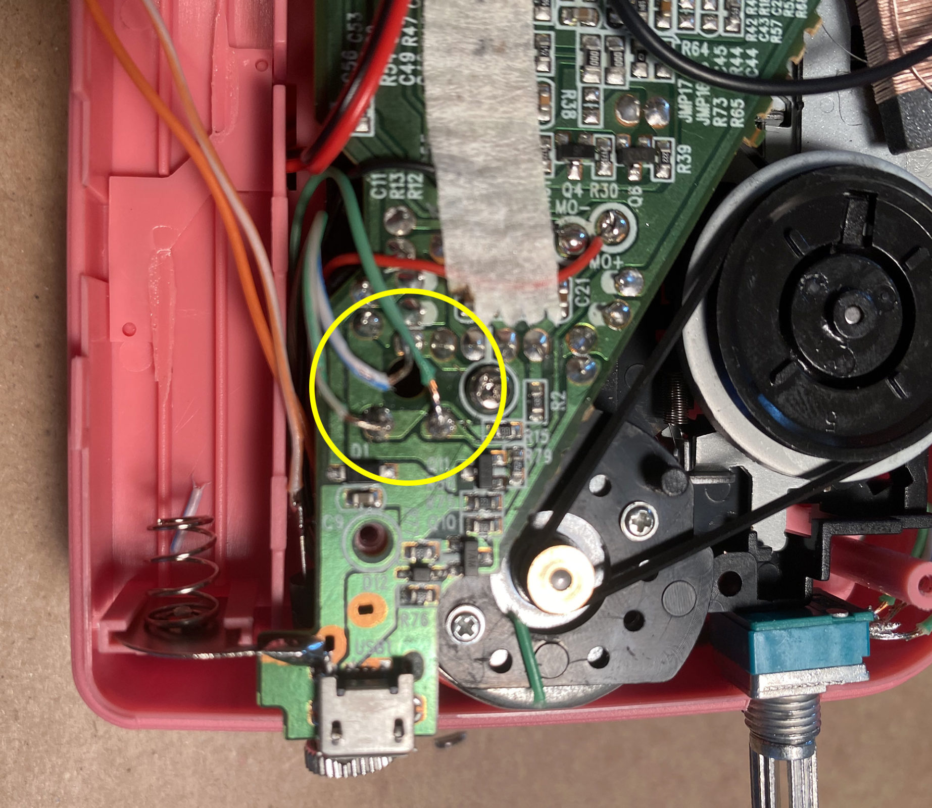
      The line in will need a very low level input to avoid distortion. If you want to match the levels a bit better, you’ll have to add a resistor to the line-in to bring the signal level down. Unfortunately, I’m not sure what the exact resistor value should be. Admittedly, I’m a bit of a “hack” when it comes to circuit bending. A lot of trial and error.

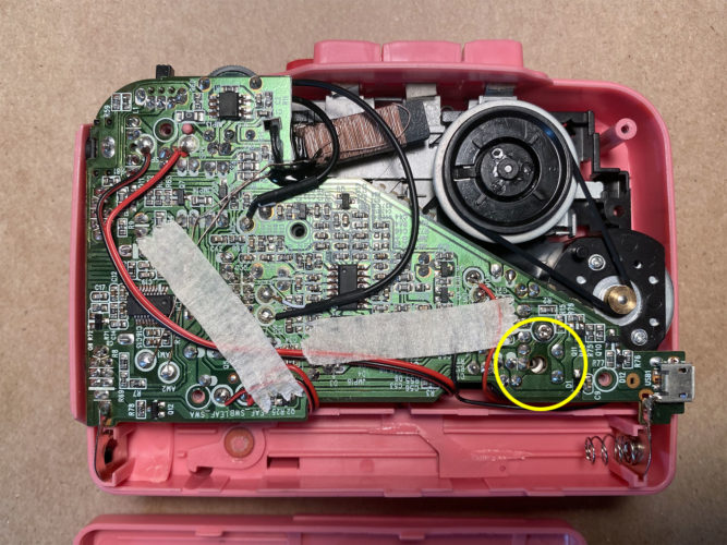
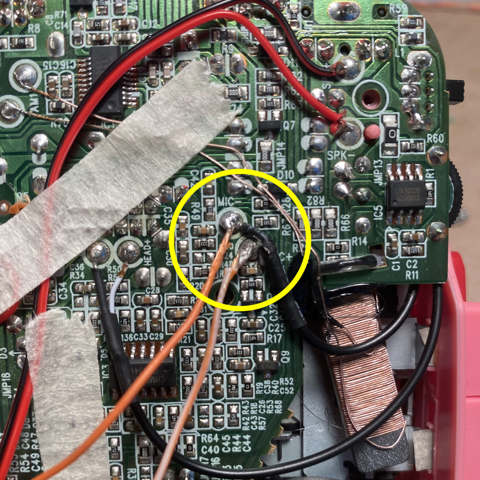
      I’ve done something similar adding a line-out to a circuit bent toy, to bring the output volume down to a reasonable level. Perhaps, I’ll revisit this tutorial and figure out the resistance that would bring the level down a bit. It’s also worth noting that since we’re just tapping off the on-board microphone, so the audio you’re capturing will likely be a mix of ambient room and line-in.

      • Martin Defatte says:

        I did a quick search and found this article describing how to add a “40 dB L-pad attenuator” to your line-in. But basically you put a 10 kohm resistor in series, and then a 100 ohm resistor to ground.

Leave a Reply to Martin Defatte